Description
Product description
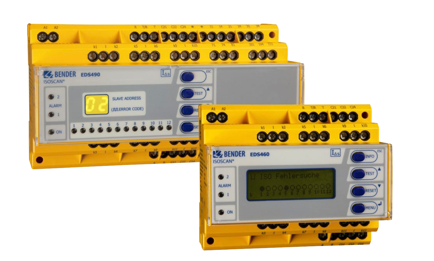
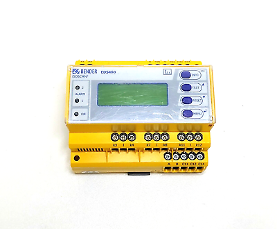
The insulation fault locators ISOSCAN® EDS460/490 in combination with the ISOMETER® IRDH575 or the locating current injector PGH are applied for localising insulation faults in unearthed systems (IT systems). The locating current signals generated by the insulation monitoring device IRDH575 or the locating current injector PGH are detected by measuring current transformers and evaluated by the insulation fault locators. Up to 12 measuring current transformers can be connected to one EDS460/490. A total of 90 EDS insulation fault locators can be connected via one RS-485 interface (BMS protocol). Hence, up to 1080 circuits can be monitored. The maximum scanning time is …10 s.
Application
• Insulation fault location in AC, AC/DC and DC IT systems
• Main and control circuits in industrial plants and ships
• Diode-decoupled DC IT systems in power stations
• Systems for medical locations
Function
Insulation fault location is started manually or automatically via the ISOMETER® IRDH575 or the PGH. Once started, the insulation fault locator EDS simultaneously scans all measuring current transformers (channels). If several EDS exist, these devices are also scanned simultaneously.
When the locating current detected by a measuring current transformer exceeds the set response value, the alarm LED 2 lights up, the common alarm relay switches and the faulty circuit is indicated as plain text on the graphical display. Version EDS…L indicates faulty outgoing circuits via alarm LEDs. The connection between the measuring current transformer and the insulation fault locator is continuously monitored. In the event of wire interruption, the alarm LED 1 lights up and the alarm relay switches. With the fault memory activated, the alarm messages of the individual channels remains stored until the reset button is pressed or until a reset command is given via the RS-485 interface. When the fault memory is deactivated, the alarm message remains stored until the insulation fault is eliminated.